Newton’s
rings are formed by the interference of light beams reflected from two
different surfaces. The phenomena is named after Isaac Newton who studied them
in 1717, where he noted an interesting ‘bull’s eye’ pattern when he placed a
curved piece of glass on a flat piece of glass.
The ‘bull’s eye’ is an interference pattern, formed due to the wave
nature of light. Below we describe how
Newton’s rings can be used as a simple method to measure the shape of soft
spheres.
To
understand the details, let us begin with a bit of ‘light and waves’ background. Light (or any wave) creates constructive
interference (bright spots) when two waves are in phase and destructive
interference (dark spots) when the waves are out of phase. If two waves are in
phase, it means that the two waves are in synchronization; both waves have
their peaks and valleys at the same location.
Out of phase means that the peaks of one wave are at the same location
as the valleys of another. A wavelength
is the distance over which the shape of the wave starts to repeat. For example, the
distance between two nearby peaks in a sine function is a wavelength. Waves also travel at
different speeds in different media. For example light waves travel faster
through air than through water and glass. We can also define
a unitless number, the index of refraction (n). It is a measure of how fast a certain
wave travels through a medium relative to the same wave traveling in a vacuum. Although
we often treat this number as a constant, the index of refraction often depends
on the wavelength used.
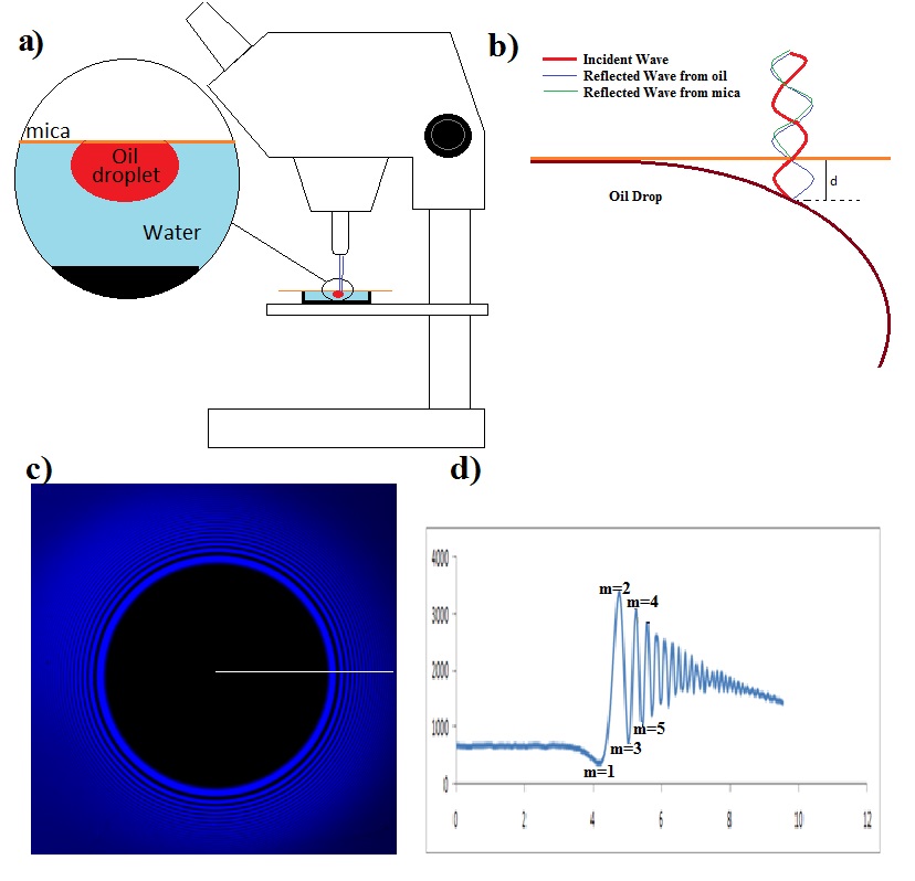 |
| Figure 1. Geometry of the experiment. (a) shows an oil drop under a microscope that is to be examined. (b) gives a schematic close-up side view of the droplet. (c) shows the actual interference picture observed (note the light and dark fringes moving out from the center contact patch (the black circle). (d) a radial average of the interferogram. |
In
our experiments we look at oil drops pushed against a thin slice of transparent
mica using a confocal microscope (Fig 1a). The microscope uses a laser light
beam, which can reflect off of any surface being observed. Our
objective is to figure out the distance, d, between the mica surface and the
drop surface using the interference pattern (Fig 1b). Note that there are two
reflected waves, one from the mica surface and the other from the surface of
the oil drop. These two reflected waves constructively interfere to form bright
rings and destructively interfere to form dark rings.
In
Fig 1c note that the outer rings are more closely packed than the inner rings,
this is because the drop surface is curving away from mica surface more rapidly
the further you get from the contact patch (dark central region).
 |
| Figure 2. Bragg scattering geometry. |
The
wave reflected from the drop surface, has to travel further than the wave
reflecting off of mica surface. Calculating this distance can be simplified by using
the geometry usually associated with Bragg’s law (Fig 2). Consider
a line between points a and c created at 90o to the incident rays,
where c is the point the first ray reflects from the topmost surface. If b is the point the second ray reflects
from the second surface, then ab is the extra distance the 2nd wave
has to travel relative to the 1st wave. Considering the symmetry after the reflection,
the total difference in distance traveled by ray 2 is 2*ab. Using a little bit
of trigonometry, we see that Sinθ = ab/d, or
ab = d*sinθ
In
short, this means that the first dark ring indicates that the second ray has traveled a difference of half of the wavelength further than the first ray,
therefore 1/2λ = 2d* sinθ. In our experiment the incident angle θ is equal to
90o, so 1/2λ = 2d and d = λ/4.
A
final detail that is important in our experiment is that the second ray travels
through a fluid, and we need to take into account the index of refraction of
water (n) which changes the effective path-length. Ultimately, d = λ/4n. The
first bright ring is due to displacement of exactly one wavelength, second dark
is due to 1.5 wavelength displacement, so on and so on.
Bright/Dark
|
m
|
d = mλ/2n
|
Dark
|
0.5
|
λ/4n
|
Bright
|
1
|
λ/2n
|
Dark
|
1.5
|
3λ/4n
|
Bright
|
2
|
λ/n
|
Dark
|
2.5
|
5λ/4n
|
In closing, if
you know the wavelength of the light source and the refractive index of the
medium in between the two surfaces, you can calculate the distance between the
two surfaces.
ReplyDeleteHi admin,
I really like it, I have also a blog which is related with you, which is about ellipsometry.
so often they contain silicone that is like spackle filling cracks on a wall.
Many of them also contain SPF which means you can't have your photo taken without a white ashy face flashing back in the final shot.
ellipsometry
Thanks,
rubel